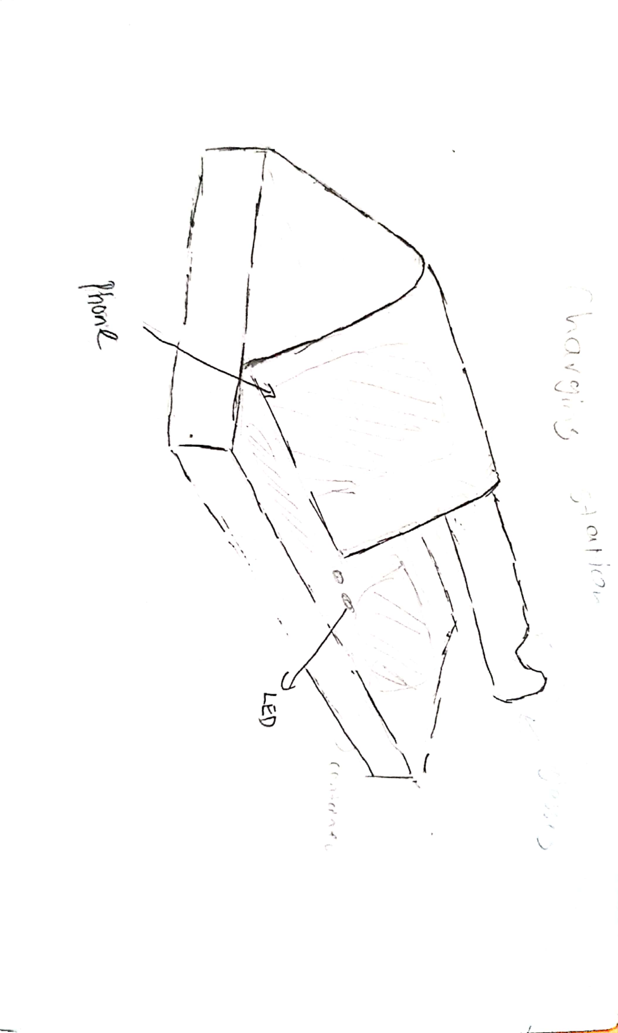
Initial Sketch
| Purpose | Choice | Reasons |
|---|---|---|
| Text Editor | Visual Studio Code | Nice looking interface, more accesibility and windows compability |
| Graphic Editor | Gimp | OpenSource image editer |
| Vector Editor | InkScape | OpenSource, rich set of features |
| Image Resizer | FastStOne Photo Resizer | windows compability,easy to use and fast |
| CAD System | Fusion 360 | Pro CAD, 3yrs Education License |
| IDE | Arduino IDE 2.0 beta | beginner friendly, write and upload programs |
| Browser | Google Chrome | Fast browser, Default browser |
Steps: Insert canvas >>> Paste image >>> Create Component(Base) >>> Trace half of the base >>>
Revolt the sketch
>>> Create Component(Knight) >>> Trace the knight >>> Extrude Symmetric
Dimension:
Base: r8.818 x 7.65
Knight: 16 x 6 x 12
CURA settings:
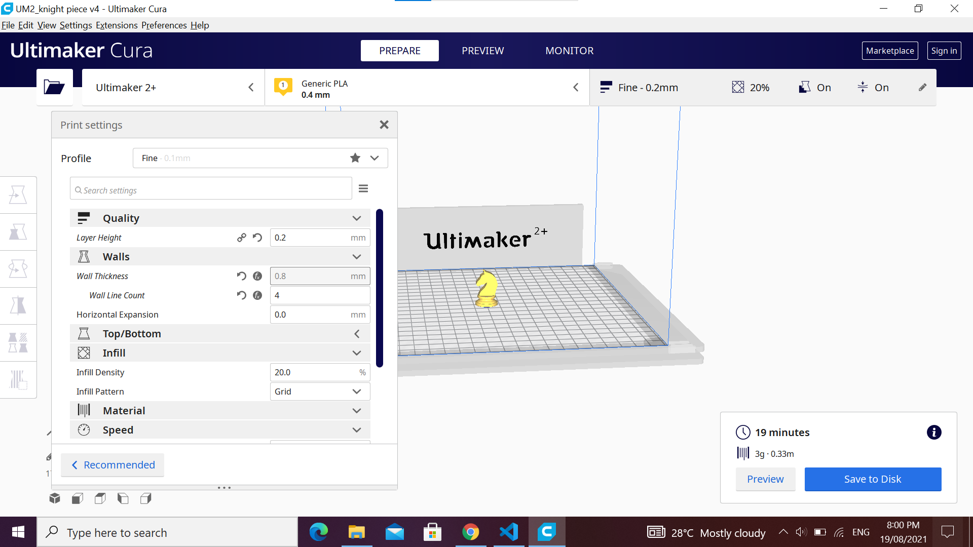
Beginning of print:
.jpg)
The first 4 layers have been successfully printed.
Print Outcome:
.jpg)
The print was successful, no printing error occur. The structure was rigid and the support were in place.
Final Outcome:
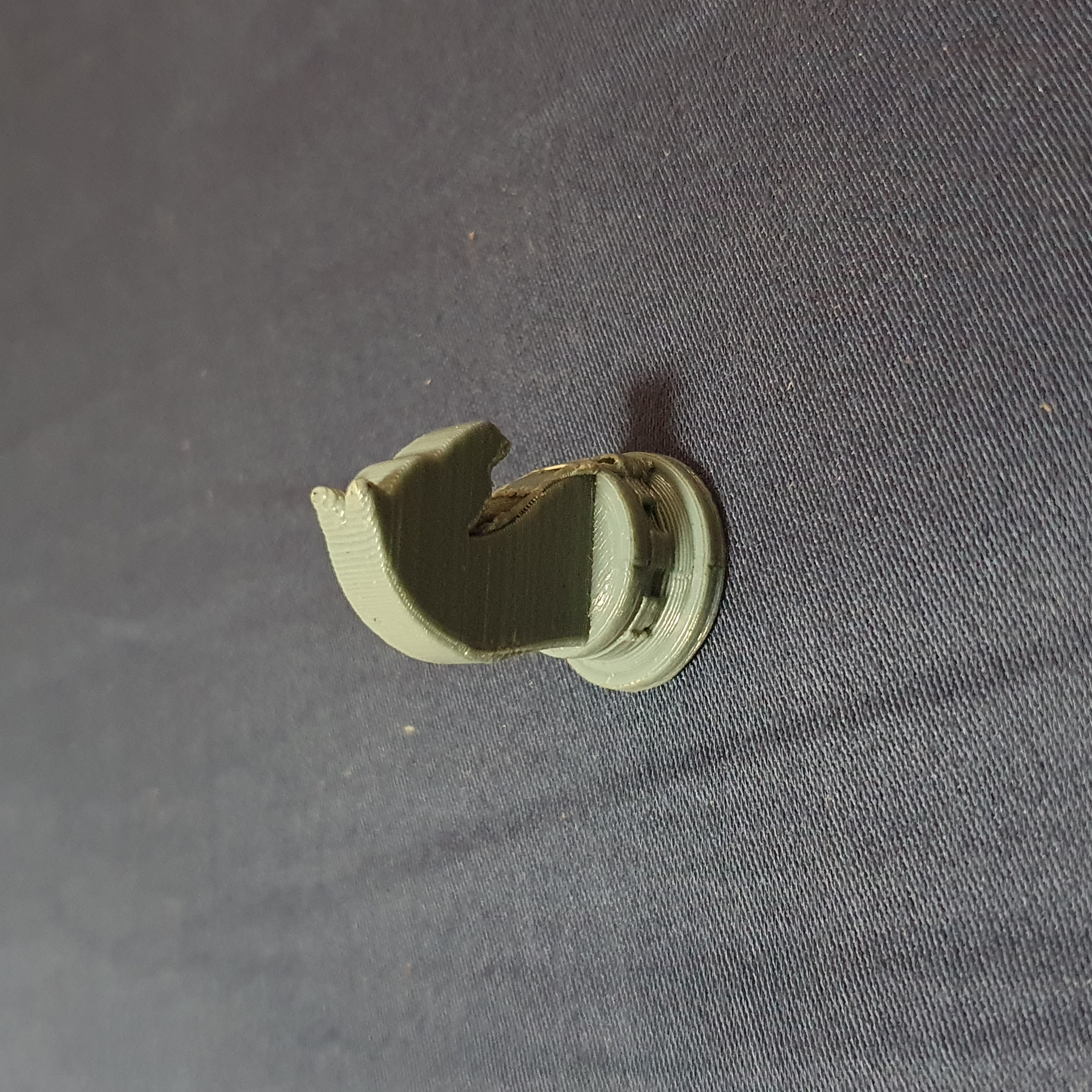
I remove the support using a piler and sanding down the rough bits. I also learn that i can use hot air to remove it too.
Create a sketch of a rectangle with joints at each sides (Side Wall) >>> Repeat sketch step for (Front Wall) >>> Extrude and combine the walls >>> create midplane on each wall >>> mirror the side wall using the front wall midplane >>> repeat step for front wall using side wall midplane >>> create the bottom wall and combine >>> design the top
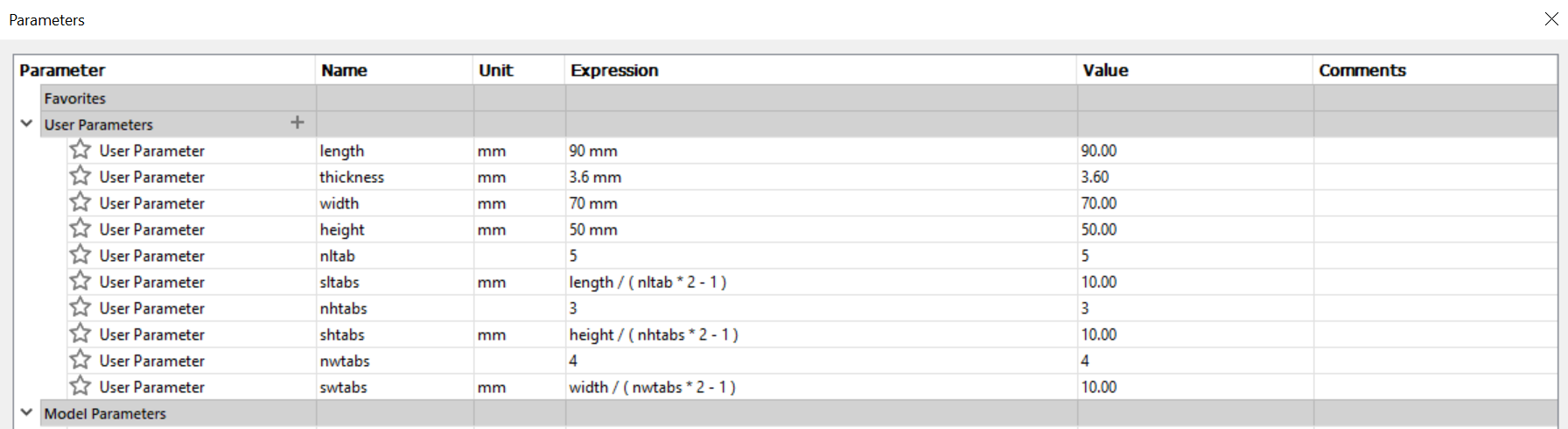
Dimension:
90mm x 70mm x 50 mm
Parameters:
Laser Cut:
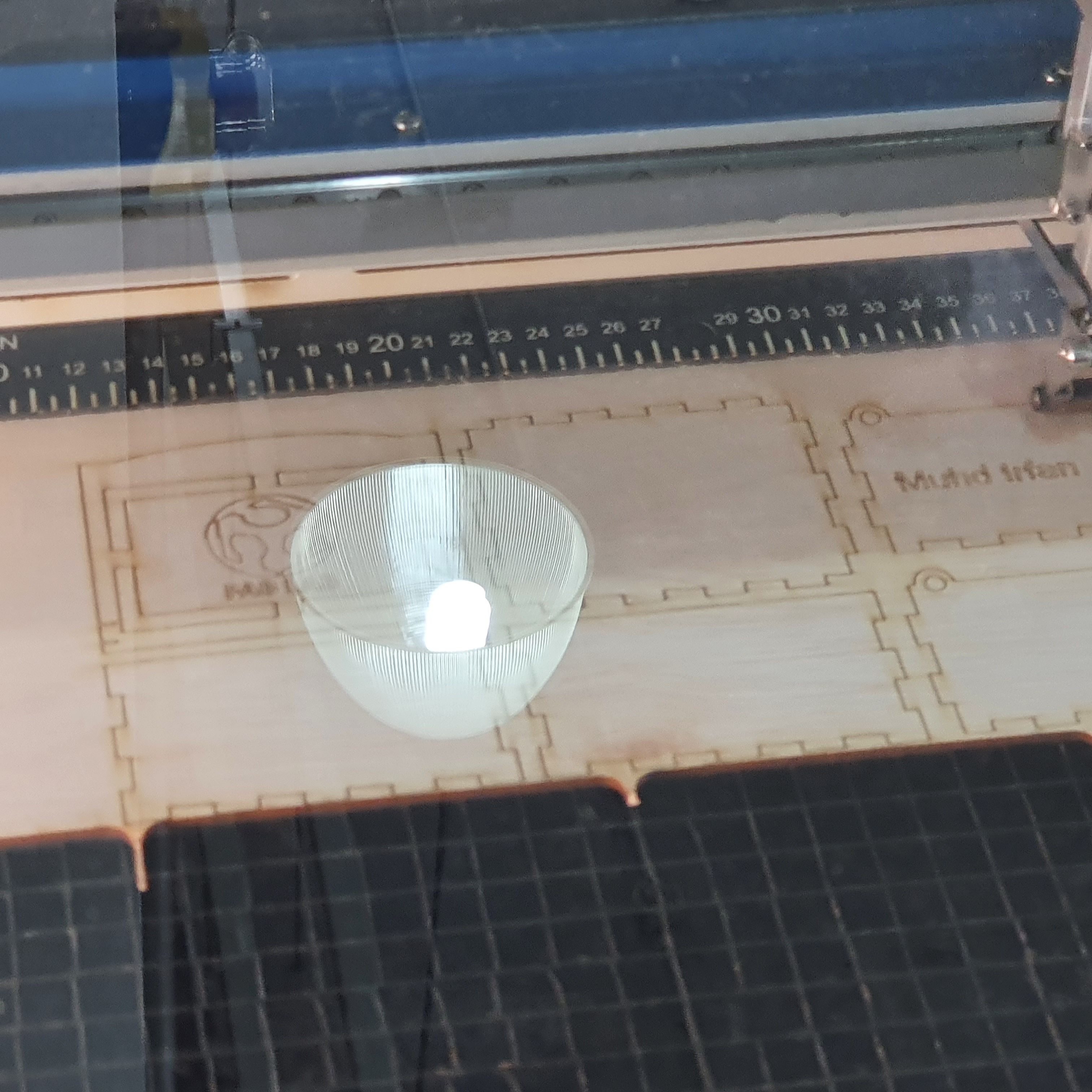
The wood thickness is 3.6mm. The settings for the print to cut is Auto Focus,Power:90%, Speed:10% ,Frequency:10% and Air assist on.
The settings to engrave is Power:90%, Speed:40%. The first cut didnt cut through, repeating the cut, the engrave
cause burn marks, to counter this i sand it to remove the burn mark.
Final Outcome:
.jpg)
I secured the box using super glue and cut the holes for the music box.
The 555 timer ic is used to create delay or pulse in the circuit. In this diagram, once the voltage is activated, the trigger signal is also activated. Therefore, led will turn on. The trigger pin is connected to the treshold pin and a polarized capacitor. Since the polarized capcitor is connected to the trigger pin, the capacitor will charge up. Once it reach a certain level of charge, it will send a signal to the treshold. Which will then turn off the led. Internally, the treshold signal will then activate the discharge trigger. The discharge signal will cause the polarized capcitor to discharge, after which it will the trigger signal is activated again, creating a endless loop.
The way this circuit works is that the arduino act as the brain of the circuit. Each time the push button is press, it will on one led and turn off the others. This cycle can be repeated 3 times before the cycle repeats itself. The specs for this circuit is push switch is the input and LEDs as output.